|
|
|
Kto jest w sklepie?
Sklep przegląda 5984 gości |
|
Kategorie
|
|
Informacje
|
|
Polecamy
|
|
|
 |
|
|
Dla tego produktu nie napisano jeszcze recenzji!
 ;
Documentation made available quickly and It is good quality. Thanks.
TK-290
CIRCUIT DESCRIPTION
4-5. APC circuit
The APC circuit always monitors the current flowing through the RF power amplifier (IC801) and keeps a constant current. The voltage drop at R35, R37, and R39 is caused by the current flowing through the RF power amplifier and this voltage is applied to the differential amplifier (IC7 1/2). IC7 (2/2) compares the output voltage of IC7 (1/2) with the reference voltage from IC3, and the output of IC7 (2/2) controls the VGG of the RF power amplifier to make the both voltages to same voltage. The change of power high/low is carried out by the change of the reference voltage. Q7, Q9, and Q13 are turned on in transmit and the APC circuit is active. (See Figure 7)
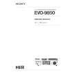
�VC LPF 14 IC5 PLL UL CPU IC406 28 DT,CLK,LE 8 IC6 �V L800 VCO CV BUFF Q3 5 X1 VCXO TO IC604 To mixer IC3 FC Q5 BUFF D602,603 SW To drive amp
Fig. 9
PLL block diagram
5. PLL Frequency Synthesizer
The frequency synthesizer consists of the VCXO (X1), VCO (L800), PLL IC (IC5) and buffer amplifiers. The VCXO generates 16.8MHz. The frequency stability is within ± 2.0ppm (temperature range of �30 to +60°C). The frequency tuning and modulation of the VCXO are done to apply a voltage to pin 1 of the VCXO. The output of the VCXO is applied to pin 8 of the PLL IC. The VCO of TK-290 covers the 38MHz spread, setting frequencies in r1, r2 (receive) and t1, t2 (transmit) with a bias voltage applied to the �V terminal of the VCO. A zero (0) volt bias is applied at frequencies lower than r1, t1. Frequencies r1, t1 through r2, t2 are biased with �3 volts. Frequencies higher than r2, t2 are biased with �6 volts, and at 174MHz tp 178MHz are biased with �9 volts. The relation of VCO frequency versus PLL lock voltage is shown in Figure 11. The output of the VCO is amplified by the buffer amplifier (Q3) and routed to the pin 5 of the PLL IC. Also the output of the VCO is amplified by the buffer amplifier (Q5) and routed to the next stage according to T/R switch (D602,603). The PLL IC consists of a prescaler, fractional divider, reference divider, phase comparator, charge pump. This PLL IC is fractional-N type synthesizer and performs is the 40 or 50kHz reference signal which is eighth of the channel step (5, 6.25 or 7.5kHz). The input signal from the pins 1 and 5 of the PLL IC is divided down to the 40 or 50kHz and compared at phase comparator. The pulsed output signal of the phase comparator is applied to the charge pump and transformed into DC signal in the loop filter (LPF). The DC signal is applied to the pin 4 of the VCO and locked to keep the VCO frequency constant. PLL data is output from DT (pin 85), CLK (pin 84) and LE (pin 93) of the microprocessor (IC406). The data are input to the PLL IC when the channel is changed or when transmission is changed to reception and vice versa. A PLL lock condition is always monitored by the pin 30 (UL) of the microprocessor. When the PLL is unlocked, the UL goes low.
r1 t1 r2 t2 512
Frequency (MHz)
Fig. 10 CV voltage vs frequency
CV voltage
6. Power Supply Circuit
Battery +B is supplied via a 3A fuse from the battery terminal connected to the TX-RX unit. After passing through the power switch power supply (SB) is applied to the two AVR ICs, and AVR circuit. IC401 supplies 5V (5CM) to the control circuit. IC402 supplies 5V (5M) to the common circuit. AVR circuit (Q400, Q402, Q405, Q406) supplies voltage to the TX circuit and the RX circuit. 5C is common 5V and output when SAVE is not set at off. 5R is 5V for reception and output during reception. 5T is 5V for transmission and output during transmission.
5V REG SB IC402 5M
SW Q401 5TC CLK DT STB1 5CC 5RC
SW Q402,400,405
5T 5C
SHIFT REGISTER 1 IC400
SW Q406
5R
5M OE DAT
Fig. 11
Power supply circuit
20
|
|
|
> |
|