|
|
|
Kto jest w sklepie?
Sklep przegląda 5424 gości |
|
Kategorie
|
|
Informacje
|
|
Polecamy
|
|
|
 |
|
|
Dla tego produktu nie napisano jeszcze recenzji!
 ;
Dokładna dokumentacja, pomogła w szybkiej naprawie telewizora. Dziękuję!
 ;
jedyne do czego mogę mieć zastrzeżenie to jakość zdjęć zawartych w przesłanej instrukcji serwisowej ponieważ są fatalnej jakości, praktycznie nieczytelne. tak poza tym jestem zadowolony to jest to czego szukałem.
;
Wszystko w porządku.
Instrukcja czytelna i kompletna.
Dziękuję.
all right!
thank you.
;
Bardzo dobra instrukcja. Zawiera wszystko co potrzeba, polecam!
;
Instrukcja jest OK. Schematy czytelne, opisane niektóre procedury.
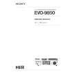
TK-385
CIRCUIT DESCRIPTION
The output signal from the summing amplifier passes through the D/A converter (IC8) again and goes to the VCO modulation input. The other output signal from the summing amplifier passes through the D/A converter (IC8) again for the BAL adjustment, and the buffer amplifier (IC1 (2/2)), and goes to the VCXO modulation input.
EXT. MIC IC13 12 HPF 15 ALC 16 MUTE Q13 SW Q300 SW MIC Q17 MIC MUTE IC8 D/A I5 O5 IC7 (1/2) SUM AMP IC8 D/A I2 O2 IC8 D/A I1 O1 A1 VCO IC1 BUFF AMP X1 VCXO D8 LIMIT IC25 (1/2) LPF 18 19 LPF DTMF
5. Frequency Synthesizer Unit
5-1. Frequency synthesizer
The frequency synthesizer consists of the VCXO (X1), VCO (A1), PLL IC(IC14) and buffer amplifiers. The VCXO generates 16.8MHz. The frequency stability is 1.5ppm within the temperature range of -30 to +60�C. The frequency tuning and modulation of the VCXO are done to apply a voltage to pin 1 of the VCXO. The output of the VCXO is applied to pin 8 of the PLL IC. The TK-385�s VCO consists of 2VCO and covers a dual range
6
MIC
9 HPF
8 PRE EMP IDC
COMP
of the 425.15~475.15MHz and the 470~520MHz. The VCO generates 425.15~475.15MHz for providing to the first local signal in receive. In TX, the pin 3 of the VCO goes low and the VCO generates 470~520MHz. The output of the VCO is amplified by the buffer amplifier (Q16) and routed to the pin 5 of the PLL IC. Also the output of the VCO is amplified by the buffer amplifier (Q18) and routed to the next stage according to T/R switch (D9, D23). The PLL IC consists of a prescaler, fractional divider, reference divider, phase comparator, charge pump. This PLL IC is fractional-N type synthesizer and performs in the 40.50 or 60kHz reference signal which is eighth of the channel step (6.25kHz). The input signal from the pins 5 and 8 of the PLL IC is divided down to the 50kHz and compared at phase comparator. The pulsed output signal of the phase comparator is applied to the charge pump and transformed into DC signal in the loop filter (LPF). The DC signal is applied to the pin 1 of the VCO and locked to keep the VCO frequency constant. PLL data is output from DT (pin 75). CP (pin 19) and EP (pin 47) of the microprocessor (IC19). The data are input to the PLL IC when the channel is changed or when transmission is changed to reception and vice versa.
Q301
MSW
PTT LSD DI9
Fig. 6 Microphone amplifier
4-2. Drive and Final amplifier
The signal from the T/R switch (D9 is on) is amplified by the pre-drive (Q18) and drive amplifier (Q20) to 50mW. The output of the drive amplifier is amplified by the RF power amplifier (IC100) to 4.0W (1W when the power is low). The RF power amplifier consists of two stages MOS FET transistor. The output of the RF power amplifier is then passed through the harmonic filter (LPF) and antenna switch (D12, D401 is on) and applied to the antenna terminal.
ANT From T/R SW (D9) +B Q18 Pre-DRIVE AMP Q20 DRIVE AMP IC100 RF POWER AMP VDD R245 R247 R249 REF VOL (IC8) IC23 (1/2) IC23 (2/2) D12,D401 ANT SW VGG LPF
A1 T/R T/R (TX : Low) VCO CV LPF IC14
Q18 BUFF BUFF Q16 SW
D9 SW D23
To drive amp
To mixer
Fig. 7 Drive and final amplifier and APC circuit 4-3. APC circuit
The APC circuit always monitors the current flowing through the RF power amplifier (IC100) and keeps a constant current. The voltage drop at R245, R247 and R249 is caused by the current flowing through the RF power amplifier and this voltage is applied to the differential amplifier (IC23 1/2). IC23(2/2) compares the output voltage of IC23(1/2) with the reference voltage from IC8, and the output of IC23(2/2) controls the VGG of the RF power amplifier to make the both voltages to same voltage. The change of power high/low is carried out by the change of the reference voltage. Q22,23 and 25 are turned on in transmit and the APC circuit is active. 8
UL CPU IC19
5 PLL 18 8 VCXO DT,CP,EP X1
MB IC1
FC
BAL
Fig. 8 PLL block diagram
|
|
|
> |
|